Overview
The 2015 ASUS Z97-E Full-Size ATX Desktop Motherboard is an Intel Z97 chipset-based desktop motherboard designed for Intel LGA1150 processors. It belongs to the Haswell and Broadwell-era desktop platform and is built around a full-size ATX printed circuit board with standard desktop expansion, storage, memory, power, and rear I/O interfaces.
From a computer hardware perspective, the board represents a mainstream-to-performance desktop motherboard of its generation. From an electronics recycling and scrap identification perspective, it is a mid-to-high-grade desktop motherboard because it contains an Intel CPU socket with dense gold-plated contact structures, DDR3 DIMM slots, PCIe expansion slots, a platform controller hub, voltage regulation components, storage connectors, rear I/O ports, audio and network ICs, BIOS firmware memory, and multilayer copper-bearing PCB material.
This board should not be confused with laptop motherboards or server motherboards. It does not contain a soldered mobile CPU or a soldered discrete GPU. Instead, it uses a replaceable socketed desktop CPU interface and expansion slots for add-in graphics cards. Its scrap value depends heavily on whether the CPU socket, chipset, expansion slots, rear I/O connectors, VRM section, and onboard integrated circuits remain intact.
Motherboard Identification
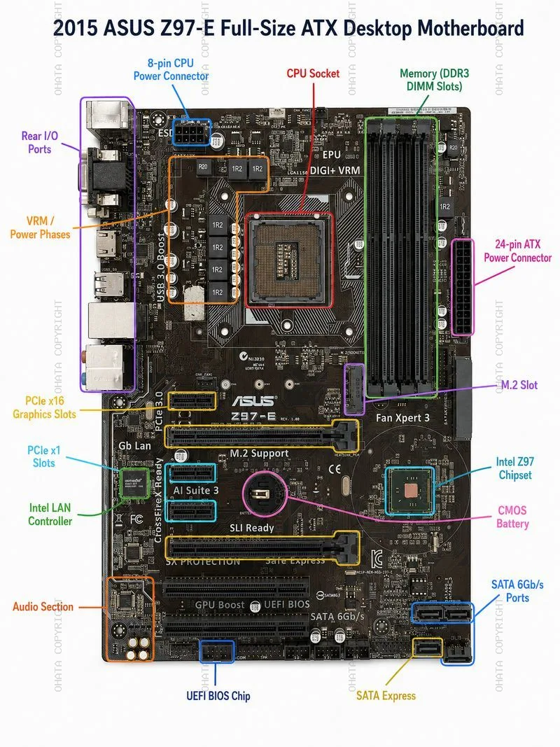
The board can be identified by the ASUS branding and the printed model marking “Z97-E” on the front side of the PCB. It is a desktop motherboard using the Intel Z97 platform and the LGA1150 CPU socket. The PCB layout shows four DDR3 memory slots on the right side, PCIe expansion slots across the lower half, rear I/O ports on the left edge, a 24-pin ATX power connector on the right edge, and an 8-pin CPU power connector near the upper-left CPU power area.
asus z97 e full size atx desktop motherboard Show All
Common visible identification features include:
- ASUS logo printed near the center of the board
- Z97-E model marking on the PCB
- Intel LGA1150 CPU socket
- Four DDR3 DIMM memory slots
- Intel Z97 PCH chipset area
- Multiple PCIe expansion slots
- M.2 Socket 3 storage connector
- SATA Express and SATA 6 Gb/s connectors
- Intel gigabit LAN controller
- Realtek audio section
- UEFI BIOS chip
- ATX form factor layout
For scrap identification, the most important visual confirmation is the complete front side of the motherboard. The front side contains nearly all of the higher-value electronic components, including the CPU socket, chipset, memory slots, PCIe slots, VRM power components, rear I/O connectors, and storage interfaces. The back side mainly shows solder joints, PCB traces, through-hole points, and socket reinforcement structures; it is useful for confirming board integrity but is not enough by itself to evaluate component completeness.
Form Factor and PCB Construction
The ASUS Z97-E is a full-size ATX motherboard. Its approximate board dimensions are 30.5 cm × 21.8 cm, or 305 mm × 218 mm. The board is narrower than some full-width 305 mm × 244 mm ATX boards, but it follows the ATX desktop layout with rear I/O on one edge, expansion slots along the lower half, and standard ATX power connectors.
The PCB is a multilayer fiberglass-epoxy board containing copper layers, plated vias, solder mask, and component pads. Desktop motherboard PCBs typically contain valuable copper in internal and surface layers. The value of the bare PCB is lower than the value of a complete board with intact components, but the PCB still contributes recoverable copper and trace precious metals through plated contacts and soldered component structures.
The board should be graded as a desktop computer motherboard rather than a simple low-grade control board. It contains dense circuitry, high-speed signal routing, several gold-contact connectors, and integrated semiconductor components. These characteristics generally make it more valuable than appliance boards, power supply boards, or low-density consumer electronics boards.
CPU Socket and Processor Interface
The CPU interface is one of the most important features of this motherboard. The ASUS Z97-E uses an Intel LGA1150 socket, also known as Socket H3. LGA means Land Grid Array. In this design, the socket on the motherboard contains the contact pins, while the compatible CPU has flat contact pads on the underside. This differs from PGA designs, where the CPU carries pins, and from BGA designs, where the chip is soldered directly to the board.
The required CPU socket type is:
- Socket type: Intel LGA1150
- Socket family: Socket H3
- Contact count: 1150
- CPU package interface type: LGA, not PGA and not BGA
- CPU package size: approximately 37.5 mm × 37.5 mm
The CPU package size is important for scrap identification because it helps distinguish LGA1150 desktop CPUs from other Intel desktop generations and from laptop BGA processors. The square LGA1150 package format also explains the shape and scale of the motherboard socket area.
The motherboard supports Intel processors from the 4th Generation Core platform and later compatible LGA1150 processors, depending on BIOS support. Typical supported processor families include Core i7, Core i5, Core i3, Pentium, and Celeron processors designed for the LGA1150 platform. Some boards in this chipset family may also support selected 5th Generation Broadwell desktop processors after the correct BIOS update.
For recycling, the socket area is especially important because the LGA contact field contains a dense array of fine metal contacts, typically gold-plated or precious-metal-bearing at the contact surface. A damaged or removed CPU socket reduces board value because it removes one of the clearest high-density recovery areas and may indicate rough handling or stripping.
A CPU may or may not be installed when the board enters the scrap stream. If a compatible CPU remains installed, the board may carry higher recovery or resale value. If the CPU has been removed but the socket is intact, the board is still a valuable desktop motherboard scrap item. If the socket is physically damaged, burned, heavily corroded, or removed, the grade may be reduced.
Memory Interface
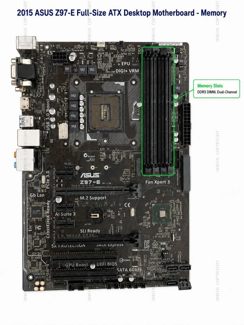
The ASUS Z97-E uses DDR3 desktop memory. It has four DIMM slots arranged vertically on the right side of the board. These are standard full-size desktop DIMM slots, not laptop SO-DIMM slots.
Memory specifications include:
- Memory type: DDR3 SDRAM
- Slot type: 240-pin DDR3 DIMM
- Number of slots: 4
- Channel architecture: Dual-channel
- Maximum supported memory: 32 GB
- Standard frequencies: DDR3 1333 MHz and DDR3 1600 MHz
- Overclocked memory support: higher DDR3 OC frequencies depending on CPU, memory kit, and BIOS settings
The memory slots are valuable in scrap because they contain many fine metal contacts. Although each slot contains only a small amount of precious metal, four complete DIMM slots together contribute to connector recovery value. They also serve as an important visual identifier for desktop motherboard grade.
asus z97 e full size atx desktop motherboard DDR DIMM
The board should be described as DDR3, not DDR4 or DDR5. Misidentifying the memory generation can create conflict in a wiki entry because DDR4 boards use different slot keying, electrical characteristics, and later chipset generations. For the ASUS Z97-E, DDR3 is the correct memory category.
Memory modules, if present, should be removed and sorted separately only if the recycling process requires component-level separation. Complete motherboards with RAM still installed may have higher resale or recovery value, but loose RAM modules are usually valued as their own material category. If the RAM slots themselves are broken, missing, or stripped from the motherboard, the board may be downgraded.
Graphics and Expansion Slots
The ASUS Z97-E does not contain a permanently mounted dedicated GPU chip. Graphics capability depends on either the integrated graphics engine inside a compatible Intel CPU or on an add-in graphics card installed into the PCI Express expansion slots.
The primary graphics interface is a PCI Express x16 slot. The board also includes additional PCIe and legacy PCI expansion options.
Typical expansion layout includes:
- PCIe x16 graphics slots
- PCIe x1 slots
- Legacy PCI slots
- Multi-GPU support depending on configuration and installed graphics cards
The key graphics-related scrap identification point is the long PCIe x16 slot. This slot is designed for desktop graphics cards and contains gold-plated internal contacts. The presence of full-length PCIe slots increases the recovery value compared with simpler low-grade control boards.
Because this is a desktop motherboard, the correct wording is “graphics slot” or “PCIe x16 graphics expansion slot,” not “onboard GPU chip.” The board may provide rear video outputs such as VGA, DVI, and HDMI, but those outputs rely on a CPU with integrated graphics. If the CPU installed lacks integrated graphics, the rear video ports may not function without a separate graphics card.
In scrap grading, PCIe slots are important because they contain plated contacts and indicate the board’s desktop computing category. Removed, broken, or heavily damaged PCIe slots reduce the board’s component completeness. However, the absence of an add-in graphics card does not mean the motherboard itself is incomplete, because the graphics card is a separate removable device.
Chipset and Platform Controller Hub
The core chipset on this board is the Intel Z97 PCH, or Platform Controller Hub. The Z97 chipset manages many platform-level functions, including storage, USB, PCIe connectivity from the chipset side, system management, and communication with the CPU. On the motherboard, the chipset is located in the lower-right quadrant of the board, traditionally under or near a heatsink area. In the uploaded board image, the chipset package area is visible because the heatsink appears to have been removed.
For scrap identification, the chipset is one of the most important semiconductor components on the board. It contains silicon, copper, package materials, solder connections, and possible precious-metal-bearing internal structures. A complete board should retain the chipset IC. If the chipset package has been removed, the board should be considered stripped or downgraded.
Key chipset identification:
- Chipset: Intel Z97
- Component type: Platform Controller Hub
- Package style: Soldered IC package on the motherboard
- Function: Platform I/O and system controller functions
The chipset should not be confused with a dedicated graphics processor. On this desktop motherboard, the Z97 PCH is a chipset, not a GPU. It is nevertheless a high-value recognition point for scrap sorting because removed chipset ICs are a common sign of component harvesting.
Storage Interfaces
The ASUS Z97-E includes a mix of transitional desktop storage interfaces from the 2014–2015 platform period.
These include conventional SATA, SATA Express, and M.2.
Main storage-related features include:
- SATA 6 Gb/s ports
- SATA Express connector
- M.2 Socket 3 connector
- RAID support for common Intel chipset RAID modes
The SATA 6 Gb/s ports are used for standard 2.5-inch and 3.5-inch SATA hard drives and SATA SSDs. These ports are usually located along the lower-right edge of the motherboard. SATA connectors contain copper alloy contacts and plastic housings. They contribute modest recovery value and help confirm that the board is a desktop storage platform board.
SATA Express was a transitional interface intended to increase storage bandwidth by combining SATA-style connector design with PCIe-based signaling. Although SATA Express did not become a long-term mainstream storage standard, its presence is useful for identifying the board’s generation.
The M.2 connector is a more modern storage feature for this platform. On the ASUS Z97-E, the M.2 slot is listed as Socket 3 and supports storage devices using SATA or PCIe signaling, depending on configuration. M.2 connectors contain fine contacts and are valuable as part of the board’s connector set.
For wiki accuracy, this board should be described as using SATA and M.2 storage, not SCSI. SCSI is a different storage interface historically associated with servers and workstations, not the standard storage identity of this consumer ATX motherboard.
Rear I/O Ports
The rear I/O section is located on the left edge of the board when viewed from the component side in standard orientation. It contains multiple external ports, typically including USB ports, video outputs, Ethernet, audio, and legacy input options.
Common rear I/O features for the ASUS Z97-E include:
- USB ports
- RJ-45 Ethernet port
- Audio jacks
- VGA video output
- DVI video output
- HDMI video output
- PS/2 keyboard/mouse port
These rear connectors are important in scrap evaluation because they contain steel shielding, copper, nickel plating, and small amounts of gold or other plated contact materials. The RJ-45 Ethernet jack, USB ports, video connectors, and audio connectors are all useful indicators of board completeness.
Boards with rear I/O connectors intact are usually easier to identify and grade. If rear ports are removed, crushed, corroded, or stripped, the board may still have value as a PCB, but it loses some connector recovery value and may be classified as less complete.
Network Controller
The ASUS Z97-E includes an Intel I218V gigabit Ethernet controller. This controller supports wired LAN connectivity through the RJ-45 Ethernet port. The Intel LAN controller is one of the identifiable integrated circuits on the board and contributes to the board’s electronic component density.
From a scrap perspective, the LAN controller itself is a small IC and does not dominate the board’s value. However, its presence helps confirm that the board is a complete desktop motherboard rather than a heavily stripped board. The associated RJ-45 port also contains recoverable metal contacts and shielding.
Audio Section
The onboard audio section uses a Realtek ALC892 high-definition audio codec. The audio circuit is typically located near the lower-left portion of the board close to the rear audio jacks. This area may include the codec IC, audio capacitors, filtering components, and separated PCB routing for noise reduction.
Audio-related scrap value comes from:
- Audio codec IC
- Small passive components
- Audio jack contacts
- Capacitors
- PCB copper routing
The audio section has lower recovery value than the CPU socket, chipset, memory slots, or PCIe slots, but it remains part of the complete motherboard component set. A board with the audio section stripped or heavily damaged should be downgraded compared with a complete intact board.
Voltage Regulation Module and Power Delivery
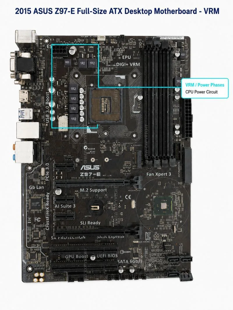
The VRM, or voltage regulation module, is the power delivery area located near the CPU socket. It includes inductors, MOSFETs, capacitors, drivers, and controller circuitry that convert power from the ATX power supply into stable voltages required by the CPU and related platform components.
asus z97 e full size atx desktop motherboard VRM
The ASUS Z97-E uses a multi-phase CPU power design, commonly identified on the board by the DIGI+ VRM marking and the cluster of square inductors near the CPU socket. The board also uses an 8-pin CPU power connector and a 24-pin ATX power connector.
Important power components include:
- 24-pin ATX main power connector
- 8-pin CPU power connector
- VRM inductors
- MOSFETs
- Solid capacitors
- Power controller circuitry
The VRM area contains copper-rich inductors and metallic components that can be valuable in large-scale recycling. It is also a sign of board completeness. Missing inductors, removed MOSFETs, burned VRM sections, or broken power connectors can reduce grade and may indicate electrical failure or component harvesting.
BIOS and Firmware Components
The board uses UEFI BIOS firmware stored in a small flash memory chip. BIOS/UEFI chips are small integrated circuits but can be useful for repair harvesting, firmware recovery, and component-level sorting.
The BIOS system may include features such as UEFI setup, EZ Flash, and recovery functions. From a scrap perspective, the BIOS chip does not add major precious metal value by itself, but it is one of the identifiable ICs that confirms the board is not heavily stripped.
A missing BIOS chip may not destroy the value of the PCB, but it reduces completeness and can make refurbishment or diagnostic reuse more difficult.
Accepted Material Condition
For recycling and scrap identification, the ASUS Z97-E motherboard is generally more desirable when it remains complete and intact.
Accepted boards should ideally include:
- Complete PCB
- Intact LGA1150 CPU socket
- Intact Intel Z97 chipset
- Complete DDR3 memory slots
- Complete PCIe expansion slots
- M.2 slot present
- SATA and SATA Express connectors present
- Rear I/O ports present
- VRM components present
- BIOS chip present
- Audio and LAN ICs present
- No major burn damage
- No severe corrosion
- No excessive attached plastic or non-electronic waste
The board may be non-working, obsolete, or removed from a desktop computer and still be acceptable as electronic scrap. Functionality is not always required for material recovery. However, completeness and cleanliness strongly affect grading.
Not Accepted or Downgraded Conditions
Certain conditions may cause the motherboard to be rejected or downgraded in scrap value.
These include:
- Removed chipset ICs
- Removed or destroyed CPU socket
- Missing major PCIe or memory slots
- Severe fire damage
- Heavy water damage or corrosion
- Broken PCB sections
- Excessive plastic housings attached
- Mixed garbage or non-electronic waste
- Swollen or attached batteries
- Oil-contaminated material
- Boards intentionally stripped of high-value ICs
- Severely bent or crushed connector areas
A board with removed chipset ICs should be treated as incomplete because the chipset is one of the key high-value semiconductor packages. Similarly, a board with the LGA1150 socket removed loses an important precious-metal-bearing contact area.
The CMOS coin-cell battery should generally be removed before final processing or shipment where battery removal is required. Batteries are not the same category as motherboard scrap and must be handled according to battery recycling procedures.
Value Factors
The scrap value of the 2015 ASUS Z97-E motherboard depends on its condition and component completeness.
CPU Socket Completeness
The LGA1150 CPU socket contains a dense field of contact pins. An intact socket increases recovery value and confirms platform identity.
CPU Presence
If a compatible CPU remains installed, the value may increase. CPUs are usually sorted separately because they contain valuable package materials and contact surfaces.
The Intel Z97 PCH should remain attached. A missing chipset is a major downgrade condition.
Memory Slot Condition
Four intact DDR3 DIMM slots add connector value and confirm the board as a desktop motherboard.
PCIe Slot Condition
Long PCIe x16 slots and smaller PCIe x1 slots contain plated contacts. Broken or removed slots reduce value.
Connector Density
Rear I/O, SATA, SATA Express, M.2, power connectors, and headers all contribute to the board’s recoverable metal content.
VRM and Copper Components
Inductors, copper traces, power circuitry, and PCB layers contribute copper recovery value.
Cleanliness
Dry, clean boards without excessive dust, oil, corrosion, or mixed material are easier to grade and process.
Preparation Tips
Before sending this motherboard into a recycling or recovery stream, the following preparation steps are recommended:
- Keep the board dry.
- Do not remove the chipset IC.
- Do not break or cut the CPU socket.
- Remove loose plastic housings if they are not part of the board.
- Remove batteries if required by the processor or buyer.
- Separate desktop motherboards from laptop boards and power supply boards.
- Keep CPUs, RAM modules, and add-in cards separate if they are graded separately.
- Avoid unnecessary stripping of slots and ICs.
- Package boards to avoid cracked PCBs and bent connectors.
The goal is to preserve the board’s original component set. A complete motherboard is easier to identify and usually grades better than a stripped PCB with missing ICs and connectors.
Scrap Grade Assessment
The ASUS Z97-E is best described as a mid-grade to upper mid-grade desktop motherboard scrap item. It is more valuable than low-density appliance boards because it contains a CPU socket, memory slots, PCIe connectors, chipset, storage connectors, rear I/O, and dense multilayer PCB construction. It is generally less valuable than server motherboards, telecom boards, or high-end workstation boards because it has only one CPU socket, standard consumer desktop density, and no server-class multi-socket architecture.
A complete board with CPU and memory installed may grade higher than a bare but intact motherboard. A board with the chipset removed, CPU socket damaged, or major connectors stripped should be downgraded.
Summary
The 2015 ASUS Z97-E Full-Size ATX Desktop Motherboard is an Intel Z97-based ATX desktop motherboard using the Intel LGA1150 CPU socket. Its CPU package interface is LGA, with a 37.5 mm × 37.5 mm CPU package size. The board supports DDR3 DIMM memory, PCIe x16 graphics expansion, M.2 Socket 3 storage, SATA 6 Gb/s, SATA Express, Intel gigabit LAN, Realtek HD audio, UEFI BIOS, and ATX power delivery through 24-pin and 8-pin power connectors.
For scrap identification, the most important features are the intact CPU socket, Intel Z97 chipset, DDR3 memory slots, PCIe slots, rear I/O ports, storage connectors, VRM power section, BIOS chip, and multilayer copper-bearing PCB. The board should be accepted and valued as desktop motherboard scrap when these components remain complete. Removed chipset ICs, damaged sockets, stripped connectors, severe corrosion, battery contamination, or broken PCB sections may reduce value or cause rejection depending on grading standards.